More information about the stepper motors:
Principle
of operation ;
Stepper motors
The two phase bipolar and
four-phase unipolar motors are available in the lab. To drive the steppers one can use the
SN754410 quadruple half-h drive; (the pdf file describing this ic is sn754410.pdf). The stepping sequence for both types of
motors can be the same as long as the connections are done properly, (please
see the following diagram).
The test program for driving
the steppers is provided (stepper.asm).
Motor voltage 5 – 15 V PP4 PP2 PP1 PP0
![]()
![]()
![]()
![]()
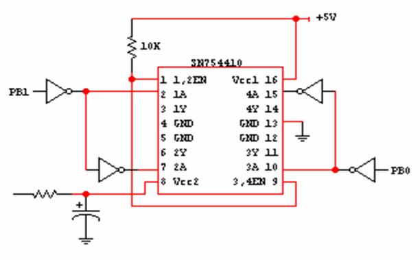
For the 2-phase bipolar motors
- connect the blue wire to 1Y, red wire to 2Y, white wire to 3Y, and yellow to
4Y.
For the 4-phase unipolar
motors - connect the black wire to ground, brown to 1Y, red to 2Y, white to 3Y,
and green to 4Y.
The
motor power supply is connected via the decoupling RC circuit to Vcc2. One should use a small
resistor for current limiting even though you do not need any voltage drop for
5V motors. When calculating the resistance
of this resistor, keep in mind that the circuit activates two phases at a
time. As you can use only ¼ watt
resistors on the breadboard; connect several resistors in parallel to get the
appropriate wattage. And, as these
resistors may heat up, position them few mm above the board. Check the rating for the capacitor, you will
need at least 15V capacitor for 12V operating voltage. Be careful when the capacitor is charged, do
not re-insert it into the circuit before the charge is dissipated.
Examples of the experiments
you can do with the stepper motor in the lab:
see how the motor work: there are both types type of motor disassembled for study.
measure the DC
operating voltage, resistance and inductance of the
windings
measure the step resolution, accuracy and overshoot
compare their rotating and holding torque
treat the bipolar as a transformer to find phase,
electrical resonance frequency
find mechanical resonance
frequency of the motor itself
leaking flux (the magnetic field outside the motor)
find max pulse rate (maximum angular velocity will be
releted to that).
Stepper motor technology
In
the lab, there is a disassembled two-phase permanent magnet motor (part no.
14769430-00 OY26H PL20S-020-TH03, from a 3.5 floppy diskette drive) for
demo. This motor converts electrical
pulses into discrete mechanical rotational steps. When it takes a step, it exerts maximum field
strength for rotational torque on the leading edge of the applied polarity
changing pulses to the windings. The SN754410 circuit is driven by PB0 and PB1,
as this bit(s) toggle the supply polarity to the respective winding(s). During
the on duty cycle of the pulses, the windings are energized and provide the
holding torque.
The
two windings in the two-section-stator each provide five pole pairs with an
half pole displacement within the section.
The alignment between the two sections is exactly a ¼ of a pole. Each section interacts with its permanent
magnetic rotor with the same number of pole pairs. Like
poles repel and opposite poles attract which is the interaction between the
stator and the rotor. The causes of the
interaction is the polarity change of the winding(s) equals to a ¼ of a pole
rotor movement. If there is five pole
pairs, there would be 20 steps/rev or 18º/step.
Servo motors
The stepper motor drive circuit
can be used for the servomotors. The
only modification needed is the current limiting resistor. Connect the black wire from the motor to 2Y
and the red wire to 4Y. You may find the
pwm.asm and servo.asm programs useful. The pwm is the emphasis of the
servo.asm, naturally, the pwm.asm is a
good place to start.